![]() The following procedure describes how to configure a Physical Layer tab that will determine the physical data flow progress of your protocol. Note that only a trained professional with profound understanding of connection protocols and the instrument connectivity properties can design a connection diagram.
The following procedure describes how to configure a Physical Layer tab that will determine the physical data flow progress of your protocol. Note that only a trained professional with profound understanding of connection protocols and the instrument connectivity properties can design a connection diagram.
>> To configure a physical layer of the protocol
| 1. | Perform Steps 1-4 of the procedure in section Designing the Protocol Message Layer. Enter the message translation parameters as explained in section Designing Protocol Message Layer, and then click on the Physical Layer tab. |
| 2. | The Physical Layer tab displays the default pre-defined stages with actions attached to them, which cannot be changed. However, you can modify part of the stage's parameters. To do so, select the relevant action/stage, and click on the State Configuration option to expand the Configuration pane. |
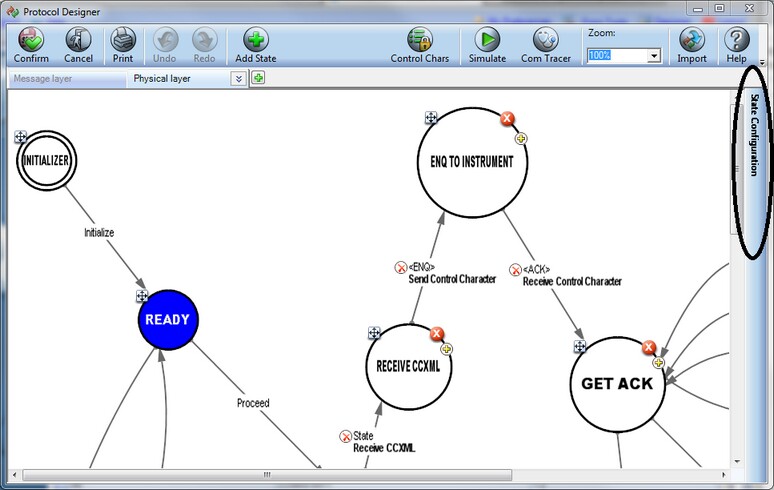
![]() TIP Be careful when you modify the default stages' settings. Each stage and action have unique properties that must be adjusted accordingly. Default stages and their properties are explained in the sub-section Data Flow Predefined Stages above.
TIP Be careful when you modify the default stages' settings. Each stage and action have unique properties that must be adjusted accordingly. Default stages and their properties are explained in the sub-section Data Flow Predefined Stages above.
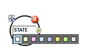
| 3. | To add a stage, click on the Add State button, and then click in the body of the window at a place where you want to situate this stage; as the stage, represented by a circle, appears, type a descriptive name for it in the box that appears in the middle of the circle, and select the color to represent the state from the given color options. |
| 4. | Click on yellow + icon to drag an action arrow to the relevant target stage, to which the machine will proceed after reaching the present stage. The right-side Configuration pane opens with configuration options for that action (and stage). |
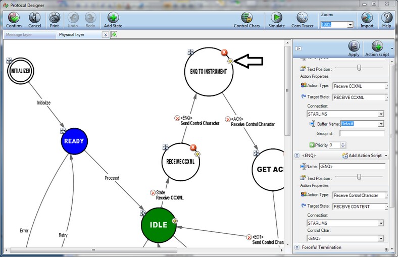
![]() TIP Use the Text Position option to adjust the stage's exact location within the flow.
TIP Use the Text Position option to adjust the stage's exact location within the flow.
| 5. | From the Action Type drop-dow list, select the relevant action that needs to be performed upon reaching this stage. See the detailed description of all existing actions in the sub-section Action Types above. According to the selected action type, the unique action properties that relate to this action only appear. Fill in these fields accordingly. |
| 6. | From the Target State drop-down list, select the target stage where the data flow will proceed upon performing this action. |
![]() TIP To add an action script to further enhance your template, click the Action Script button. For more information on action scripts, see section Action Scripts.
TIP To add an action script to further enhance your template, click the Action Script button. For more information on action scripts, see section Action Scripts.
| 7. | Add as many stages and actions as needed. After you have built your template, the data flow will have to follow a full cycle when sent from the instrument. The protocol cycle is a sequence of operations which is being initiated starting from the IDLE stage through other stages in the protocol, completing the sequence by returning back to the IDLE stage. |
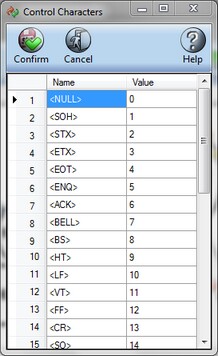
![]() TIP If needed, click on the Control Chars button to add control characters and their values to the system. Control characters are signals that define the values of the characters which are to be received by the system. For example, if the value 0 is received, it will mean <NULL>.
TIP If needed, click on the Control Chars button to add control characters and their values to the system. Control characters are signals that define the values of the characters which are to be received by the system. For example, if the value 0 is received, it will mean <NULL>.
| 8. | After finishing your work, you can test the data flow execution by simulating the flow. For more information, see section Simulating Message Transmission. |
![]() TIP Click on the arrow adjacent to the physical layer's name on the tab if you want to rename, remove or duplicate the current physical layer, and select the appropriate option from the menu.
TIP Click on the arrow adjacent to the physical layer's name on the tab if you want to rename, remove or duplicate the current physical layer, and select the appropriate option from the menu.
| 9. | To add a different physical layer, click on the green + adjacent to the physical layer's name on the tab, and configure the new physical layer's properties as described in this procedure. Click Confirm to save your configurations. |